
Troubleshooting Fiber Runs
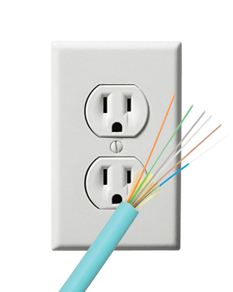
Fiber optic cabling is arguably the most reliable way to transmit audio, video, control and network signals -- it supports 10,000x times more bandwidth than twisted pair, it's immune to electromagnetic and RF interference, it's non-corrosive, and it's impervious to static electricity, lightning and power surges. However, as with copper-based installations, fiber can have challenges.
This article explores common ways to troubleshoot fiber optic installations. We'll examine:
- Necessary tools for troubleshooting
- Verifying "link budgets" and areas of loss
- Verifying proper connector terminations
- Cleaning optical connectors and equipment
- Verifying proper bend radius'
Loss & Power Budgets
Signal loss is inevitable on any cable run -- whether it's loss from cable length, inline connectors, splices, or couplers. It's critical to identify and calculate the total amount of loss on a cable run, as well as how much loss the connected devices can tolerate.
The amount of anticipated signal loss on a cable run is known as the Loss Budget. This is the amount of loss you should expect based on your configuration.
The amount of signal loss your connected devices can tolerate is known as the Power Budget. Power budgets can have a minimum and maximum rating and are often specified by the manufacturer.
The key is to ensure your power budget falls within your loss budget and that your loss budget is accurate. These variables combine to create your Link Budget.

Typical link budgets are:
- Fiber-based HDMI extenders: 3 dB
- Fiber-based AV over IP devices: 3 dB
- Network equipment: 11 dB
As indicated above, network equipment is far more forgiving to loss than AV equipment.
Troubleshooting Tip: Too Much Loss
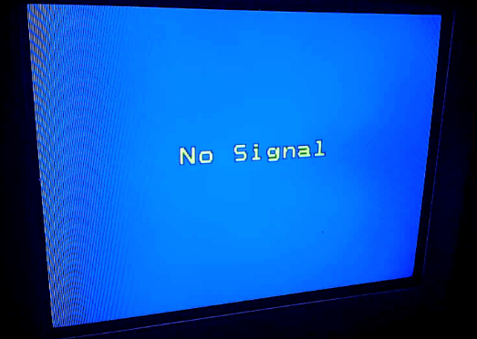
Too much loss on a cable run will create intermittent signal issues (typically image picture dropouts) or a complete lack of signal altogether. Loss is introduced from a number of areas, including connectors, couplers, splices and overall cable length.
| Common Areas of Loss | Typical Amount of Loss |
| Mechanical connectors | 0.2 - 0.5 dB |
| Factory made connectors | 0.1 - 0.2 dB |
| Mechanical splice | 0.1 - 0.5 dB |
| Wallplate keystone | 0.2 dB |
| Coupler | 0.2 dB |
| Factory premade cable | 0.3 - 0.5 dB |
| Bulk multimode fiber (per 1,000 ft.) | 0.2 dB |
| Bulk single mode fiber (per 1,000 ft.) | 0.1 dB |
Determining your link budget is as simple as identifying your points of loss, calculating the anticipated loss budget, and verifying your actual cable run's loss falls within that loss budget.
For example, an installation with HDMI over fiber extenders will have a power budget of 3 dB. In a typical residential setting, you'll have a bulk fiber run with LC connectors, a wallplate keystone, and a premade patch cord. These components combine for an anticipated loss budget of 1.3 dB -- well within the power budget.

On paper, the installation shouldn't have an issues. The final step would be verifying the actual loss with an Optical Link Test Kit. If the actual loss exceeds the anticipated loss budget, you need to look for issues in the installation such as:
- Poorly terminated connectors
- Damaged cabling
- Over stressed (such as overly bent) cabling
- Dirty connectors and/or equipment
Troubleshooting Tip: Poor Connector Termination
A common area of loss, especially for first-time installers, is poor mechanical connector termination. Assuming you're using TechLogix SSF™ connectors, a properly seated connector will have minimal light present in the locking tab window when using a Visual Fault Locator (or VFL) -- a key component of any Fiber Termination Kit.

The good news is that if you have a poorly seated connector, TechLogix SSF™ connectors are reusable and can be re-terminated in the field up to 12 times.
Troubleshooting Tip: Dirty Connectors & Equipment
Fiber connectors and installation hardware ships with dust caps to ensure optical lenses remain clean during transit and installation. It's best practice to keep these dust caps in place as long as possible to avoid dust, oils, and other contaminants from obstructing the optical lenses. Contaminants will cause loss, creating signal drops and/or a complete loss of signal altogether.
 |
|
Example of Fiber Optic Dust Caps
|
If your connectors and equipment are compromised, they can be cleaned with a fiber optic "pen-style" or "click" cleaner.
 |
|
Example of Fiber Optic Pen-Style Cleaner
|
Troubleshooting Tip: Fiber Bend Radius
A final area of loss is overly bent or crimped cable. Bending fiber too tightly will cause microfractures, leading to partial signal loss, complete signal loss, and/or failure over time. Overly bending fiber is a great way to get it to break.
The traditional rule with fiber is that its bend radius is 10x its jacket diameter (typically 30mm or 1.1 inches for most cables). And while this rule applies to "traditional" fiber, it does not apply to TechLogix SSF™ bulk fiber.
TechLogix SSF™ bulk fiber has a working bend radius of 3mm (0.11 inches). TechLogix premade bulk fibers, on the other hand, follow more traditional guidelines and have a working bend radius of 30mm (1.1 inches).

Worse Case Scenario: Broken Fiber
When testing fiber, in most cases a VFL will show some light present and an optical meter will read some signal (even if a bunch of loss is present). If no light or signal is present and your connectors look to be terminated properly, the cable could be catastrophically compromised or completely broken. A broken cable will require an inline splice to connect the two broken ends.
Comments